Synchronizing the components
Components within stages require synchronization for proper functioning.
Stage 1 components
Proceed to the Synchronize view, by clicking on the Synchronize tab from the top menu panel.
See Synchronizer page in the App Overview book to learn more about it's layout
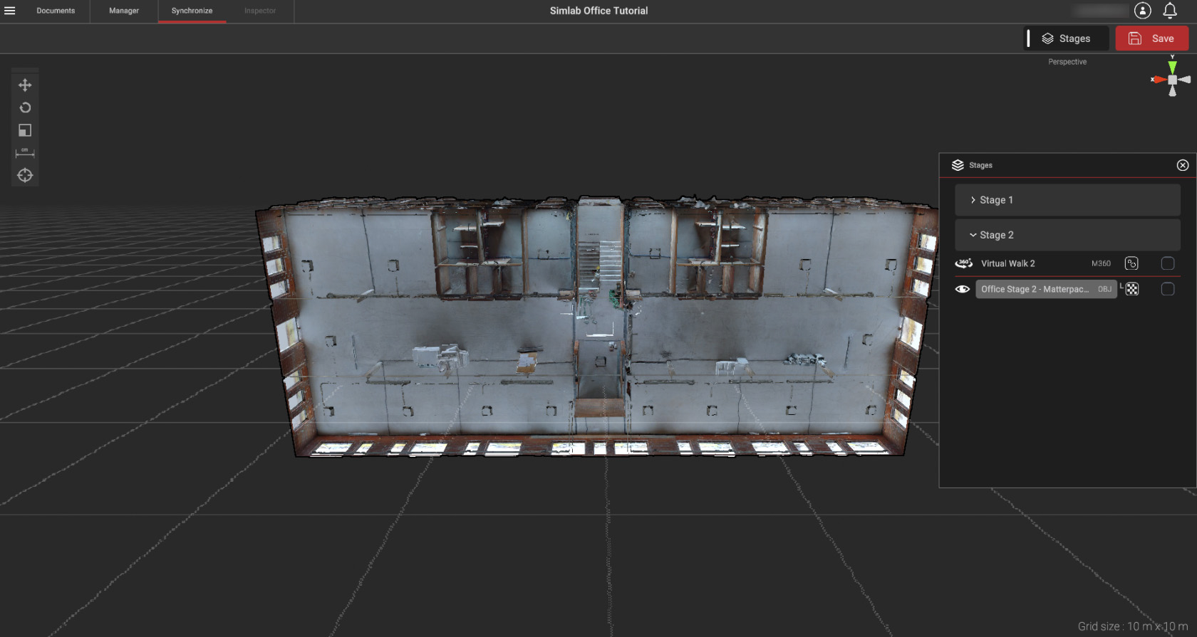
When you first open up the space, you'll most certainly see something similar to the picture above. Depending on the software used, the models will have different rotations, their centers misaligned etc. In the case above, the model was saved with the Z axis being the vertical one, while Stages uses Y axis as the vertical one. This is a natural occurrence in 3D software because of multitudes of standards different programs use.
First we'll need to set the base for the rest of the components to synchronize to. Generally it would be the first 3D scan (Matterpack) of the Stage 1. Using the "Stages window" Toggle the visibility of the Office Stage 2 to off and Office Stage 1 to on.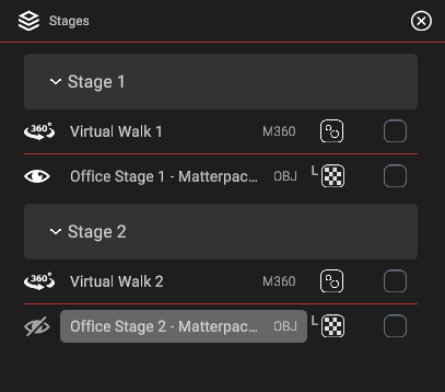
If you need help with navigating within 3D space - see 3D Navigation
3D Model Scan Rotation
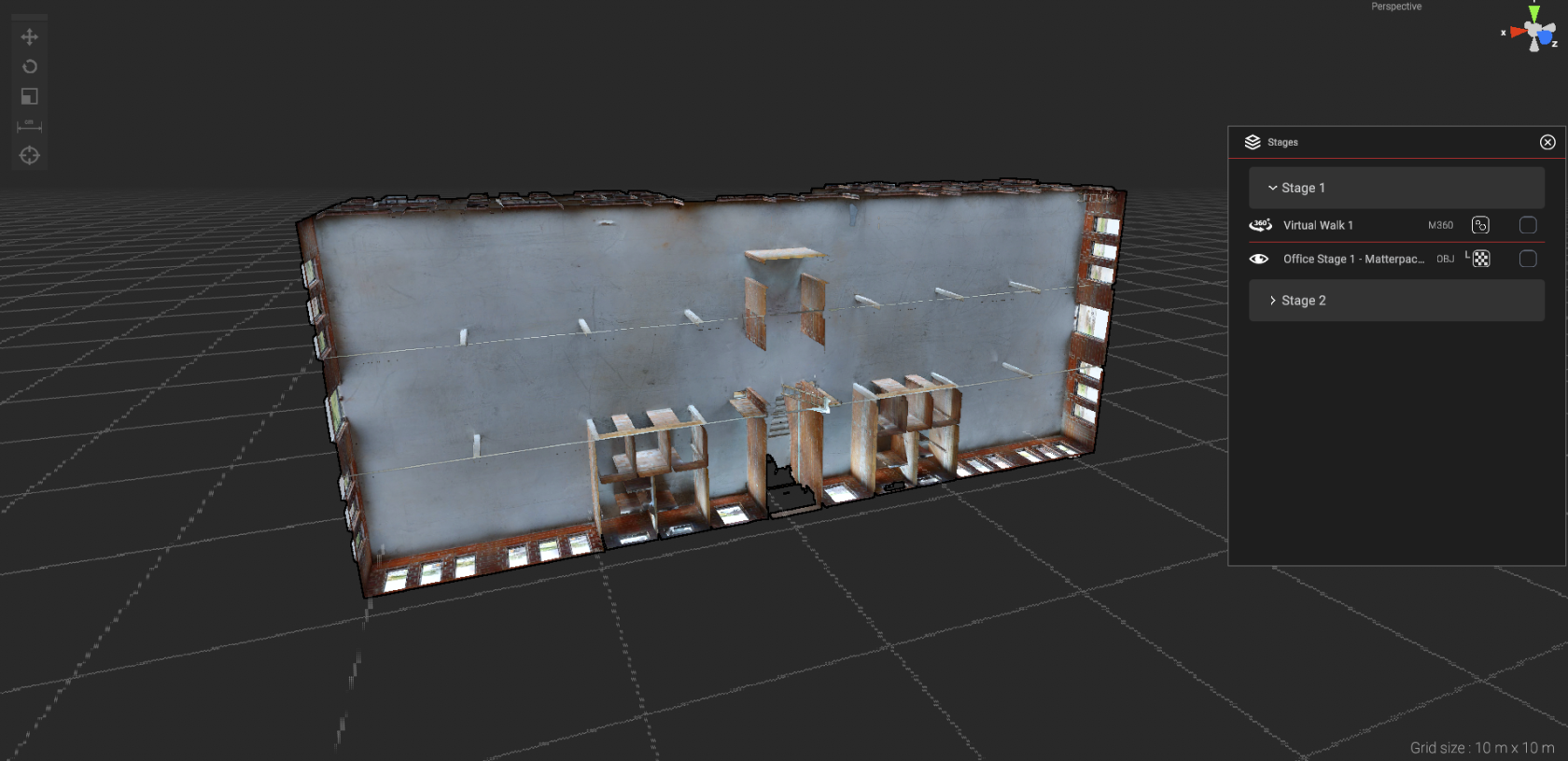 fig.1: default rotation model
Generally, setting the proper model rotation should be the first step, followed by scale and lastly position.
To proceed with these transformations, first you need to select the target. Click the "Office Stage 1" tile from the "Stages window", it should become highlighted in the window and the model will start pulsating in the viewport indicating it is selected. The transformations toolbar should become available to use now.
|
Selecting the Rotation
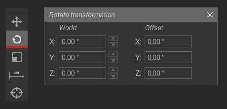
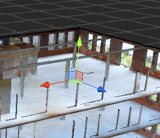
Use the gizmo and Rotate transformation window to correctly align the model within the 3D Space
|
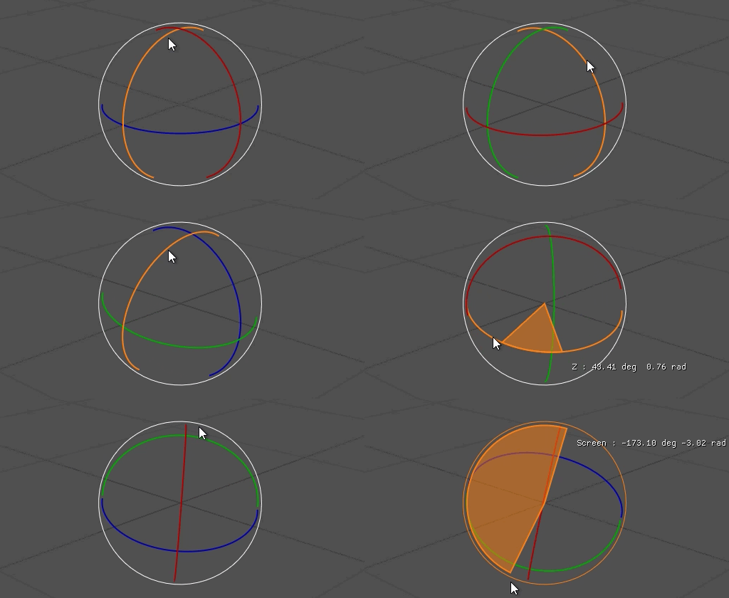 Rotation Gizmo Rotation Gizmo |
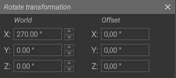
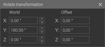
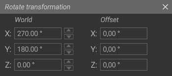
(ANSWER) Final Rotation values
|
Transformation window |
Using the provided tools, find the correct model rotation. It should look like the picture below. Here's the end result:
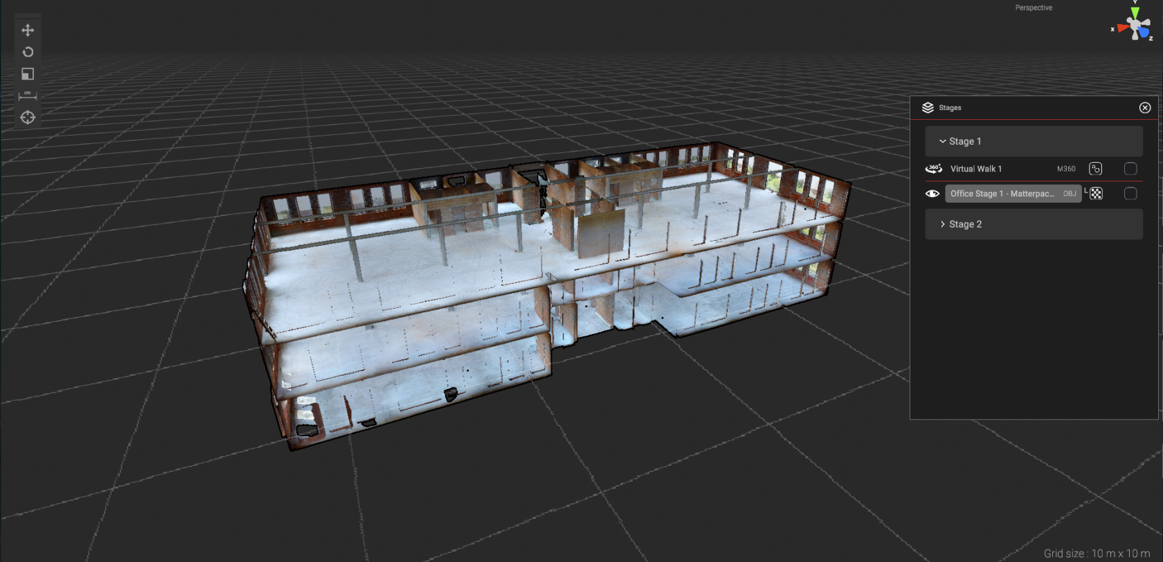 fig.2: properly rotated model
3D Model Scan Position
|
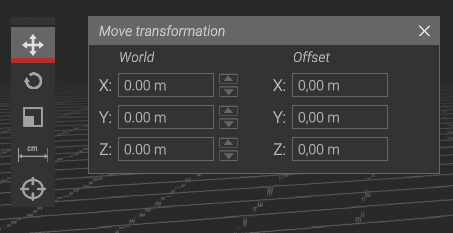
Having the model rotated to fit within the space accordingly, now we must position it to the appropriate ground level (indicated by the viewport grid.)
With the 3D scan set in place it will now act as the base for the rest of the components to be synchronized
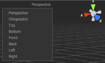
By clicking different cones from the direction indicator (located in the top right corner of the viewport) you can quickly change to one of the predefined views. Clicking the "Perspective" will reveal the list of all the views that are available to you. |
 |
|
 |
||
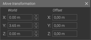
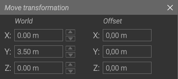
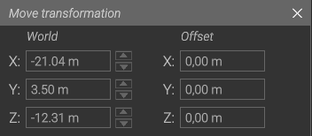
(ANSWER) Final Move transformation Values
|
 |
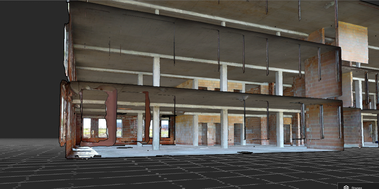
The final result should look like this:
Virtual Walk Scan Synchronization
Lastly we will attempt to position the Virtual Walk so that it represents relatively the same positions between views.
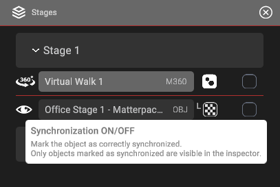
| Navigate to "Stages window" and click the |
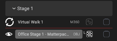 |
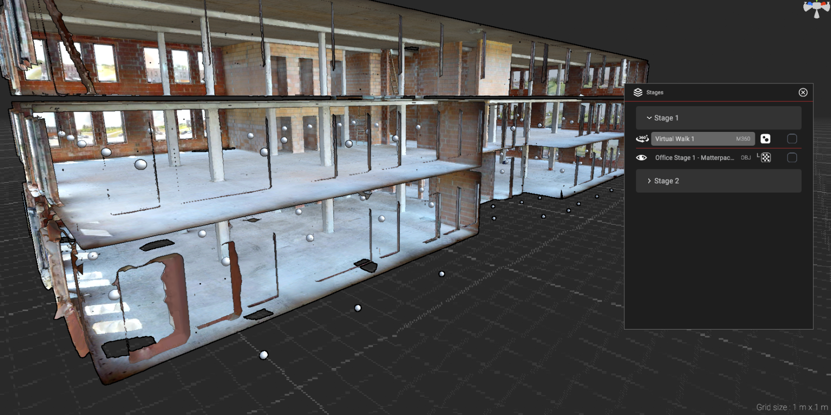 fig.1: unaligned swipes
Aligning the swipes is more challenging, considering that we must figure out correct orientation and position by comparing the swipe layout with the scan. Since the swipes are places where the scanner was positioned, to properly align the swipes with the scan, generally you ought to familiarize yourself with the Virtual Walk.
(at any time you can switch the view to the virtual walk by clicking the ![]() button.)
button.)
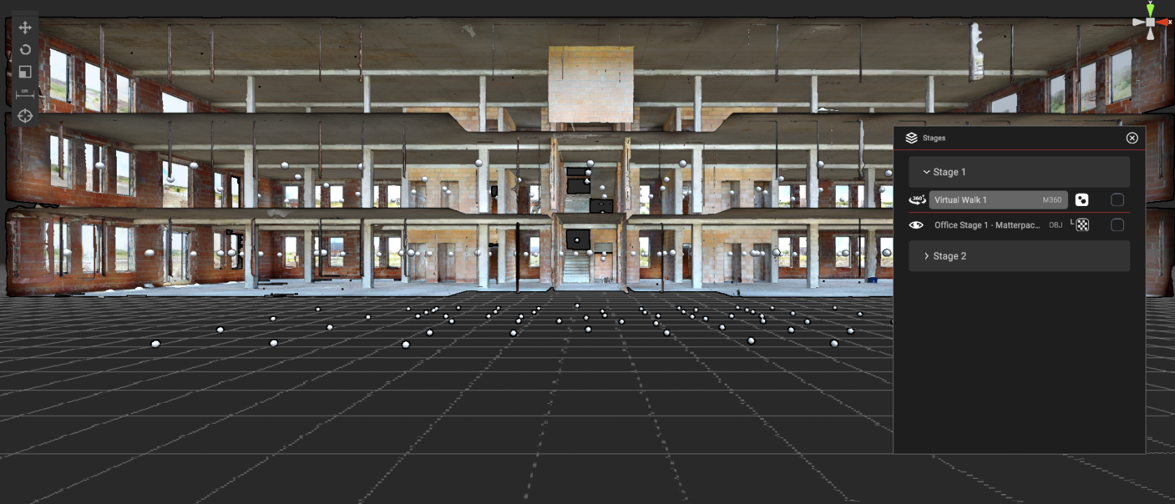 fig.2: front view
The easiest points to use as the "anchors" are swipes created near doors and multiple rooms, then averaging the alignment of them in said space. To achieve this, first you can use the predefined top/side/front views to first roughly position the swipes in one plane at a time to then view the result in multiple angles and adjust it accordingly.
|
It's not necessary to place the swipes perfectly within space, try to be reasonably precise
The swipes should also be located at roughly the same height as the scanner that was used to take the scans |
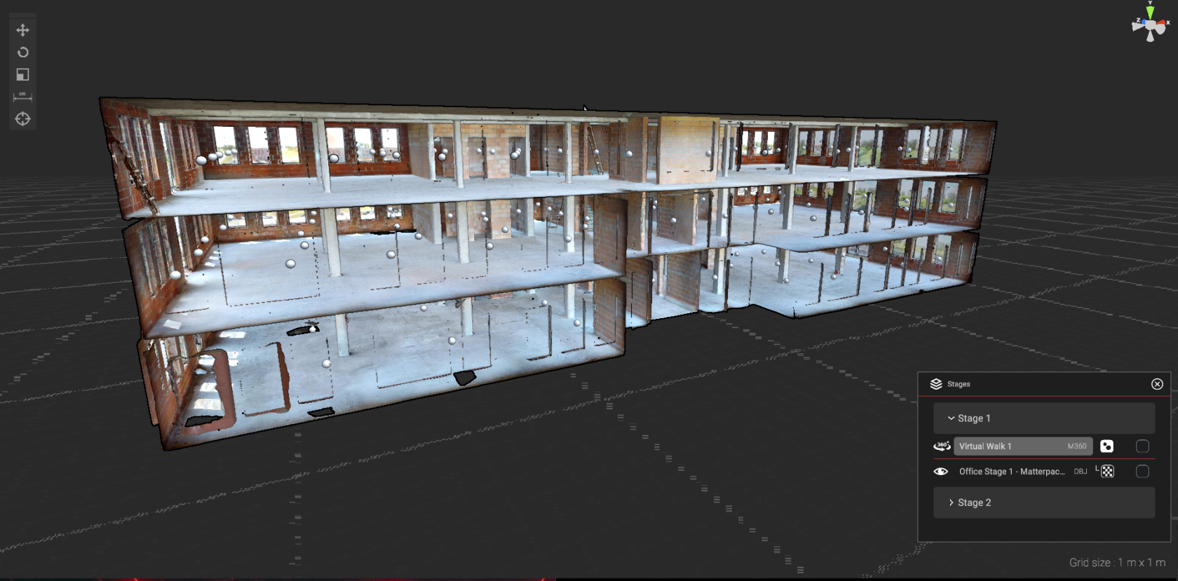 fig.3: aligned swipes
Saving the synchronization
|
With both: the 3D scan and Virtual Walk aligned, confirm the synchronization by checking the box next to both components, located in the Stages window.
Apply the changes with the |
 |
Synchronizing Stage 2
Synchronizing Stage 2 components to Stage 1 components.
|
The second stage components will be more challenging. As you will see in the following examples, their initial positions (and rotations) will be out of alignment to previously setup stage.
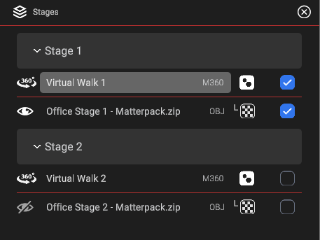
First, we'll tackle the Virtual walk swipes, since we already have setup the first one. Toggle the visibility of both: the Matterpack scan as well as both M360 swipes, from the "stages" window.
Proceed with the same steps while aligning the swipes of the second stage, but now you'll be able to use the Virtual Walk 1 swipes as an additional help. |
 |
Virtual Walk 2
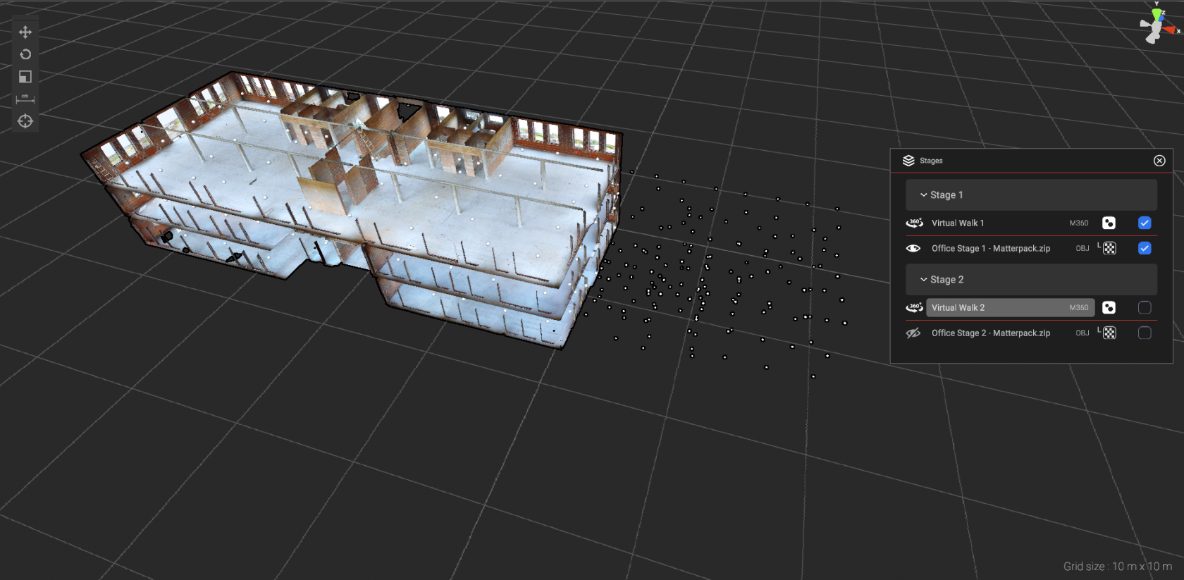 fig.1: unaligned swipes
|
Things to consider while aligning M360 swipes:
|
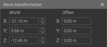
(ANSWER) Approximate Final transformation values
|
3D Model Scan 2
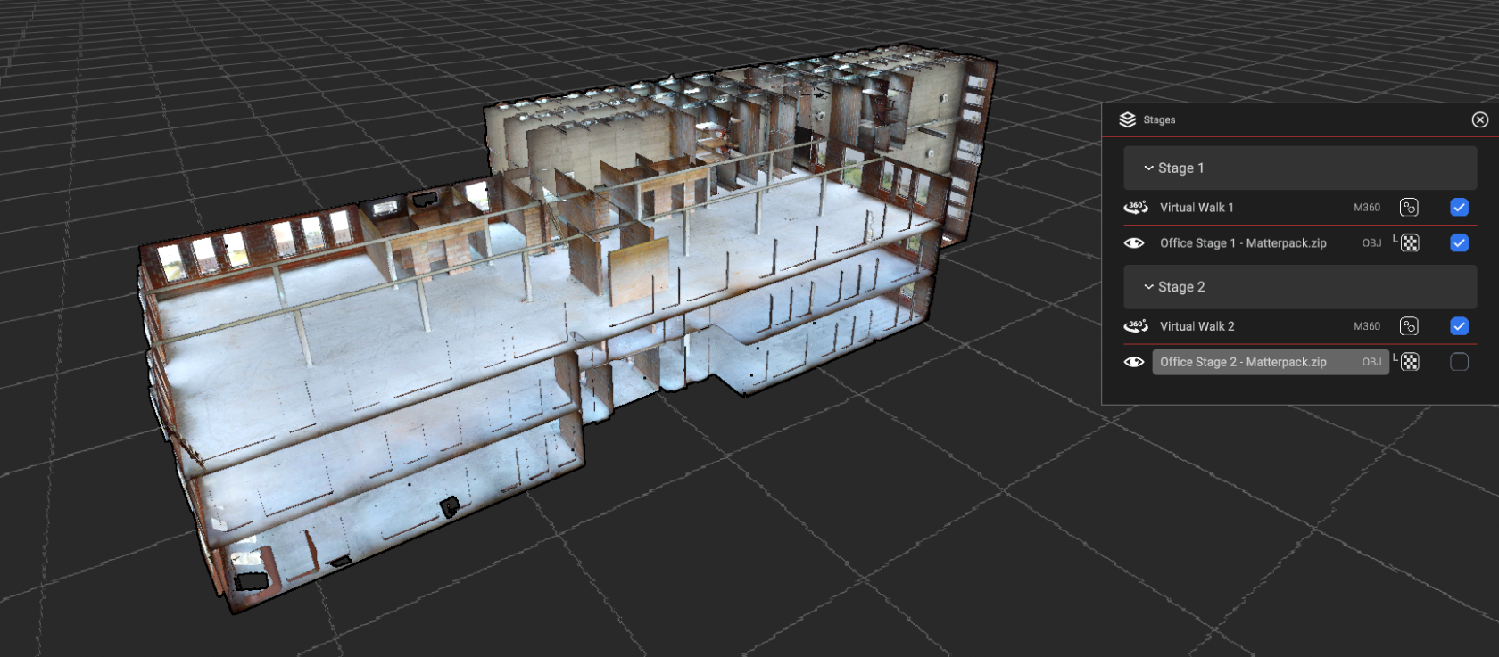 fig.2: unaligned model
|
Things to consider while aligning 3D scan models:
|
Both stages aligned:
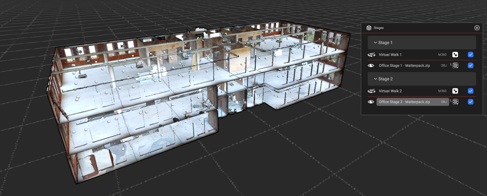 fig.3: models and swipes aligned
Remember to mark the components as synchronized!
Inspector check
Go through stages in the inspector view to check if everything works as it should.
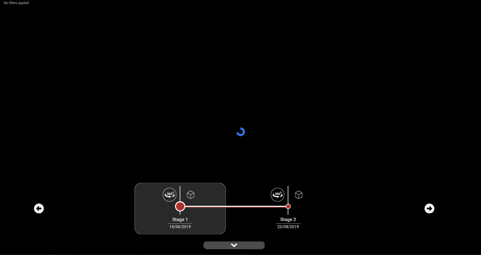
Check the components alignment in the following order:
- Stage 1: 360 View
- Stage 2: 360 View
- Stage 1: 3D View
- Stage 2: 3D View
- Stage 1: 360 View
- Stage 1: 3D View
- Stage 2: 360 View
- Stage 2: 3D View

